


 34 / 118

32
CK3300G-2
CRANE - SUPPLEMENTAL DATA
Barge (0 degree thru 3 degree machine list)
10. Boom lengths that can attach auxilialy sheave are from
78 ft (24 m) to 276 ft (84 m).
11. The boom should be erected over the front of the crawlers,
not laterally. When erecting and lowering the luffing
boom at length of 256 ft (78 m) or over, the blocks for
erection must be placed at the end of the crawlers.
12. Least stable position is over the side.
13. Maximum hoist load for number of reeving parts of line
for hoist rope.
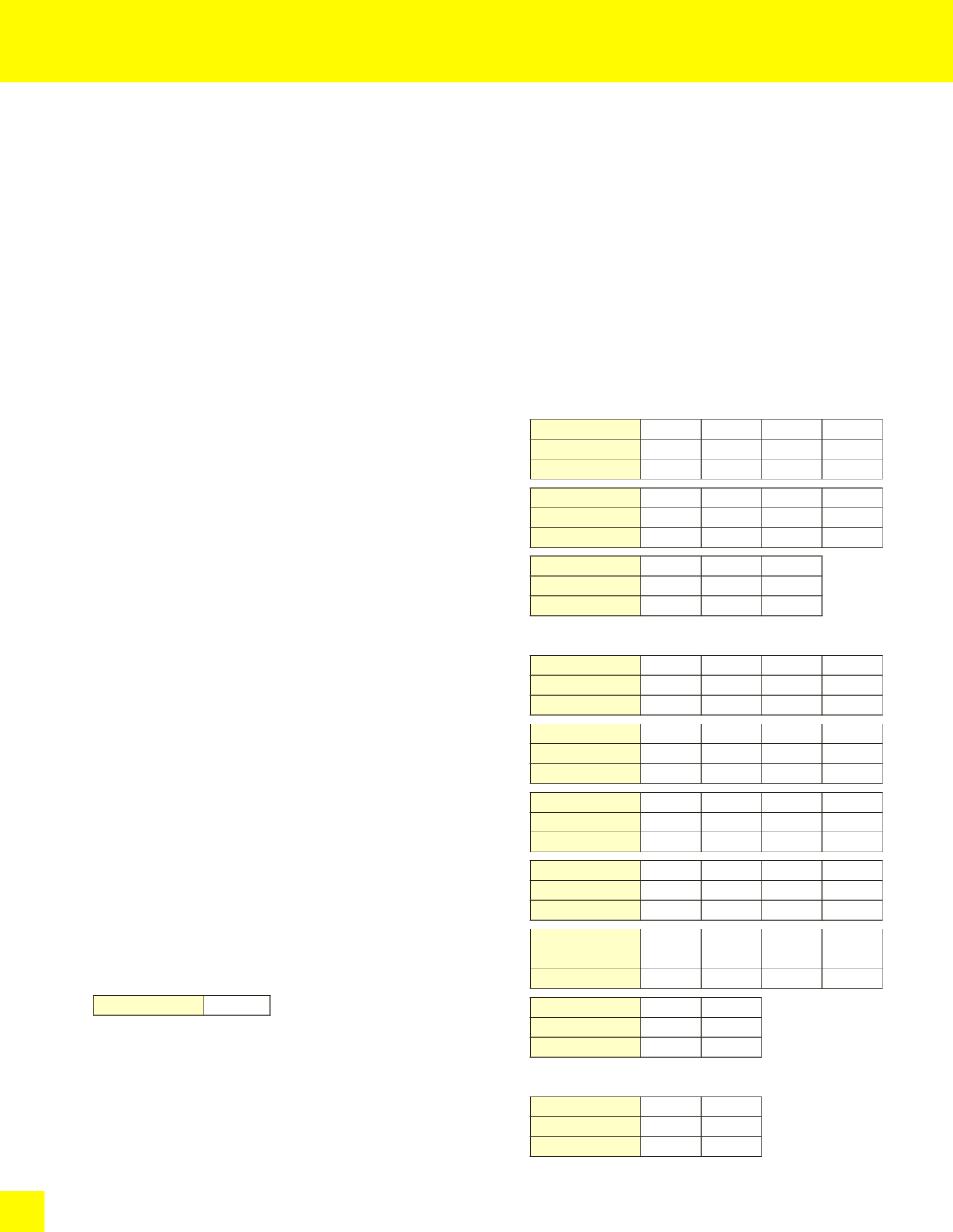
Main Boom Hoist Loads (Double Drum)
No. of Parts of line 4 (2×2)
6 (2×3)
8 (2×4) 10 (2×5)
Max. Loads : lbs 132,200 198,400 264,500 330,600
Max. Loads : t
60.0
90.0
120.0
150.0
No. of Parts of line 12 (2×6) 14 (2×7) 16 (2×8) 18 (2×9)
Max. Loads : lbs 396,800 462,900 529,100 595,200
Max. Loads : t
180.0
210.0
240.0
270.0
No. of Parts of line 20 (2×10) 22 (2×11) 24 (2×12)
Max. Loads : lbs 661,300 727,500 771,600
Max. Loads : t
300.0
330.0
350.0
Main Boom Hoist Loads (Single Drum)
No. of Parts of line
1
2
3
4
Max. Loads : lbs
33,000 66,100 99,200 132,200
Max. Loads : t
15.0
30.0
45.0
60.0
No. of Parts of line
5
6
7
8
Max. Loads : lbs 165,300 198,400 231,400 264,500
Max. Loads : t
75.0
90.0
105.0
120.0
No. of Parts of line
9
10
11
12
Max. Loads : lbs 297,600 330,600 363,700 396,800
Max. Loads : t
135.0
150.0
165.0
180.0
No. of Parts of line
13
14
15
16
Max. Loads : lbs 426,500 454,100 482,800 509,200
Max. Loads : t
193.5
206.0
219.0
231.0
No. of Parts of line
17
18
19
20
Max. Loads : lbs 536,800 562,100 588,600 613,900
Max. Loads : t
243.5
255.0
267.0
278.5
No. of Parts of line
21
22
Max. Loads : lbs 638,200 661,300
Max. Loads : t
289.5
300.0
Auxiliary Hoist Loads
No. of Parts of line
1
2
Max. Loads : lbs
33,000 66,100
Max. Loads : t
15.0
30.0
1. Rated loads included in the charts are the maximum
allowable freely suspended loads at a given boom length,
boom angle and load radius, and have been determined
for the machine standing level on firm supporting surface
under ideal operating conditions.
The user must limit or derate rated loads to allow
foradverse conditions (such as soft or uneven ground, out-
of-level conditions, wind, side loads, pendulum action,
jerking orsudden stopping of loads, inexperience of
personnel, multiplemachine lifts, and traveling with a load).
2. Rated loads do not exceed 75% of minimum tipping
loads.
Rated loads based on factors other than machine stability
such as structural competence are shown by asterisk
“
*
”
in the charts.
3. The machine must be reeved and set-up as stated in the
operation manual and all the instruction manuals if these
manuals
are missing, obtain replacements.
• Boom backstops are required for all boom lengths.
• The crane must be leveled to within 1% on a firm
supporting surface.
• Counterweights and carbody weights are fully installed.
4. Do not attempt to lift where no ratings are shown as
crane may tip or collapse.
5. Attempting to lift more than rated loads may cause
machine to tip or collapse.
Do not tip machine to determine capacity.
6. Weight of hooks, hook blocks, slings and other lifting
devices are a part of the total load. Their total weight
must be subtracted from the rated load to obtain the
weight that can be lifted.
7. When lifting over boom point with auxiliary sheave,
rated loads for the boom must be deducted as shown
below.
Auxiliary Sheave
Deductions : lbs
1,500
8. To install the jib is prohibited when the machine on the
barge.
9. The total load that can be lifted over an auxiliary sheave
is the value for 1,500 lbs deducted from rated load for
the boom without auxiliary sheave, but it should not
exceed auxiliary maximum hoist loads.