


 38 / 47

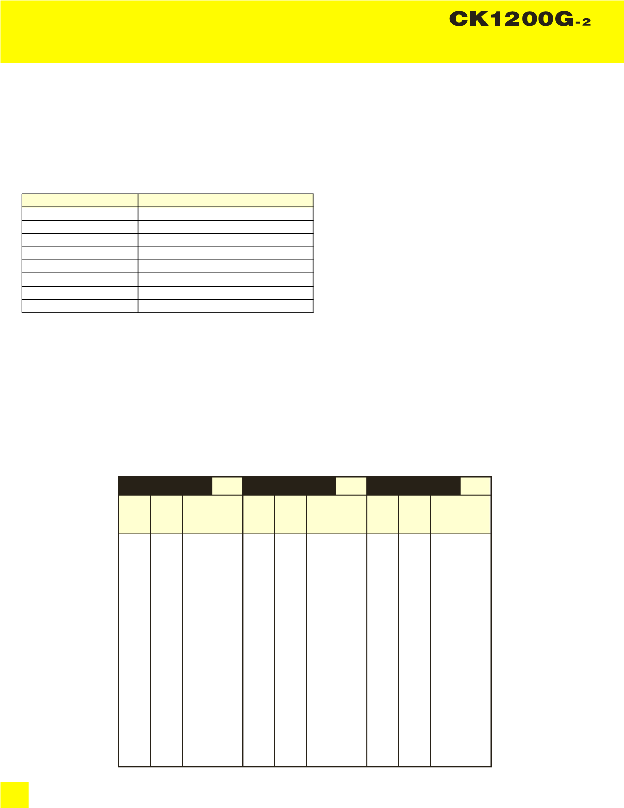
SPECIFICATIONS
36
Clamshell
Boom length ft (m)
Boom arrangement
50 (15.2)
Base-A-Tip
60 (18.3)
Base-A-A-Tip, Base-B-Tip
70 (21.3)
Base-A-B-Tip
80 (24.4)
Base-A-A-B-Tip, Base-B-B-Tip
90 (27.4)
Base-A-C-Tip
100 (30.5)
Base-A-A-B-B-Tip, Base-A-A-C-Tip
110 (33.5)
Base-A-B-C-Tip
120 (36.6)
Base-A-A-B-C-Tip, Base-B-B-C-Tip
Boom:
Welded lattice construction using tubular, high-tensile steel chords with pin connections between each section.
Basic boom length: 50 ft (15.2 m)
Max. boom length: 120 ft (36.6 m)
Limit on clamshell bucket weight: 4,600 lbs (2,100 kg)
Optional tagline: Hydraulic operated type and spring type.
Boom Component Chart:
Base = Boom Base
Insert:
A = 10 ft (3.05 m)
B = 20 ft (6.10 m)
C = 40 ft (12.2 m)
Tip = Boom Tip
1. Figures represent maximum allowable capacity, and assume level, ground and ideal working conditions.
2. Capacities are calculated at 66% of the minimum tipping loads.
3. Capacities are maximum recommended by PCSA Standard #4. Allowances must be made by the user for such unfavorable conditions as a sort of uneven
supporting surface, rapid cycle operations, or bucket.
4. The combined weight of the bucket and load must not exceed these capacities.
26.0
28.0
30.0
32.0
34.0
36.0
38.0
40.0
45.0
64.4
61.8
59.2
56.4
53.6
50.7
47.6
44.3
35.2
25,000 *
25,000 *
25,000 *
25,000 *
25,000 *
25,000 *
25,000 *
25,000 *
25,000 *
23,100
Load
Radius
(ft)
Boom
Angle
(deg.)
360
゚
Rated Load
(lbs)
50' Boom
30.0
32.0
34.0
36.0
38.0
40.0
45.0
50.0
55.0
64.8
62.6
60.4
58.2
55.9
53.5
47.2
40.2
31.9
25,000 *
25,000 *
25,000 *
25,000 *
25,000 *
25,000 *
22,900
19,800
17,400
Load
Radius
(ft)
Boom
Angle
(deg.)
360
゚
Rated Load
(lbs)
60' Boom
34.0
36.0
38.0
40.0
45.0
50.0
55.0
60.0
65.0
63.2
61.3
59.4
54.5
49.2
43.5
37.1
25,000 *
25,000 *
25,000 *
25,000 *
22,700
19,600
17,200
15,200
Load
Radius
(ft)
Boom
Angle
(deg.)
360
゚
Rated Load
(lbs)
70' Boom
3 Counterweights (50,900 lbs) - Without Carbody weights - Crawlers in extended position.
Refer to notes on page 35.